A multiplexer is a Combinational circuit (it is a type of circuit whose output rely on the given inputs using various logic gates ) that takes multiple inputs and delivers only a single output. It consists input data lines, selection lines and a single output.
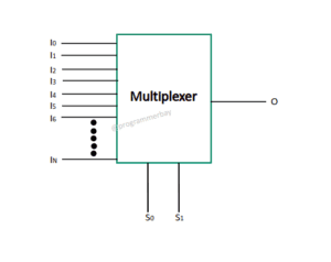
We require n selection lines, where 2n represents total input lines and n represents selection lines. (In this case, 22 that gives 4 input lines and 2 selection lines).
A multiplexer is often abbreviated as MUX or many to one circuit or parallel to serial circuit.
It is a data selector that provides the mechanism to select single binary information from many input lines and passes it to output line
Advantages of Multiplexer:–
- It is less costly and reduces transmission circuit complexity
- It can be used to implement many combinational circuits
- It reduces number of wires
Applications of Multiplexer:
- It is used in communication system i.e Satellite systems, telephone networks
- It is used to read data from memory locations in computer memory
Types of Multiplexer
There are various types of multiplexers and few are given below:
- 2:1 MUX
- 4:1 MUX
- 8:1 MUX
- 16:1 MUX
- 32:1 MUX
In this article, we’ll be discussion 4:1 MUX.
Here are the steps to design or construct 4 to 1 Multiplexer or 4:1 MUX using Logic Gates :
1) Now, make a diagram of multiplexer with 4 input lines, 2 selection lines and 1 output. In below diagram, A0 , A1 , A2 and A3 are input data lines, S0 and S1 are Selection lines and lastly one output line named Y.
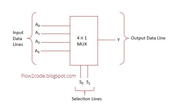
2) This is how a truth table for 4 to 1 MUX looks like . According to the truth table, the output of the multiplexer fully depends on selection lines (binary data , 00,01,10 & 11) and one input would be selected from all the input data lines as the output.
Truth table
| Selection Lines | Output | |
|---|---|---|
| S0 | S1 | Output |
| 0 | 0 | A0 |
| 0 | 1 | A1 |
| 1 | 0 | A2 |
| 1 | 1 | A3 |
Above table is created as per follow :
When S0 =0 and S1=0 , then A0 would be the output.
Similarly When S0 =0 and S1=1 , then A1 would be the output.
We can represent this by an expression.
Output = S0‘.S1‘A0 + S0‘.S1A1+ S0.S1‘A2 + S0.S1 A3
3) In last step, design 4 to 1 multiplexer by using 4 AND gates and a single OR gate.
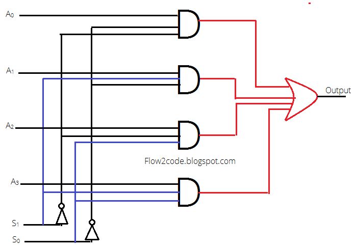
Explanation:
In above diagram, there were two selection lines along with their respective complements using Inverters. Each and every AND gate were holding three inputs from S1, S0 and a particular input A. lastly, outputs of all AND gates became the input for OR gate and providing a single output.